General Data Link Layer Frame Structure

This post briefly describes the general format of a data link layer frame. The post describes typical fields inside the MAC header, LLC header and the Frame Trailer.

This post briefly describes the general format of a data link layer frame.

The data link layer’s primary duty is to carry Network layer (L3) datagrams/packets inside frames to a next hop neighbor through a physical wired/wireless link. To achieve this, it usually takes each L3 packet and creates a frame by  encapsulating the L3 packet with a Frame header and a Frame trailer. The L3 packet is sandwiched between the Frame header and trailer.

The Frame header usually consists of frame synchronization fields like Preamble/flags, control information necessary to carry the frames to the correct next hop neighbor like L2 addresses of source and destination node, L3 Protocol Type and optional fields for flow control and reliability. The Frame trailer usually consists of a CRC/checksum of the frame contents, for error detection purposes (and in some cases error correction too) and optionally an End-of-Frame Flag.

The generic data link layer frame structure is given in the diagram below

Data link layer frame structure. While the first diagram shows the theoritical structure, the second diagram shows typical frame contents


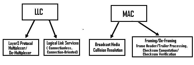
The generic frame structure consists of a MAC header, followed by a LLC header, then the actual L3 datagram to be carried to the next hop and then a MAC Trailer, as shown in the top portion of the above diagram.

The typical contents of each of these sub-blocks are shown in the bottom portion of the diagram. The MAC header and LLC header are usually combined and termed as the Frame header.  A majority of  Wired/Wireless LAN and WAN data link protocols follow the structure/format given above, though there may be a few exceptions.

Each of the sub-blocks of a typical data link layer frame is explained briefly below:

MAC header Fields

Preamble/SFD-Flag  – Each frame usually starts  with a known synchronization pattern. This pattern may be a combination of a preamble pattern, followed by a flag byte or just a flag byte alone.

In transmission, though the sender and receiver know the transmission rate apriori, the actual transmission rate at any instant, may not be constant always and may dynamically hover around this rate, due to drifts in the sender’s clock.   The preamble  is a standard sequence of multi-byte pattern, sent at the start of every frame and is used to constantly  synchronize the receiver’s clock with that of the sender, so as to make the receiver’s measured bit interval duration to be the same as that of the sender’s current bit interval duration.   In the preamble pattern, there must be enough clock transitions in known positions, so as to enable the receiver to latch onto the sender’s current clock frequency. For e.g. Ethernet uses a 7 byte pattern consisting of alternating 1’s and 0s as the preamble pattern.

The SFD (Start Frame Delimiter) Flag is another standard byte pattern agreed between the sender and receiver. The purpose of the SFD Flag is to enable the receiver to know the position of the actual frame header. On seeing the SFD flag byte, the receiver would know that the actual frame contents start immediately after the SFD flag. For e.g. Ethernet uses the SFD byte with value 10101011. Note that the last 2 bits have consecutive 1 bits. So, when a receiver receives the preamble pattern, followed by this SFD byte, it can start processing the actual frame contents starting from the byte immediately succeeding the SFD byte.

In many protocols, an explicit preamble pattern is not used and in such cases, the SFD flag is used for both clock synchronization and for frame beginning identification. For e.g. PPP does not use a preamble and only uses a SFD, with a byte value of 01111110.

Note : One may wonder as to what would happen if the L3 data itself contains the preamble/SFD-Flag patterns. To overcome the problem of the receiver mis-interpreting this as start or end of a frame, standard “bit stuffing” or “byte stuffing” techniques are used. These bit/byte stuffing techniques examine the data pattern and insert extra bits/bytes to the L3 data, whenever the L3 data has the standard preamble/SFD-Flag pattern inside it. These extra bits/bytes are then filtered out by the receiver to get the original L3 data. This way, the sender makes sure that the Preamble/SFD-Flags are unique within a data link layer frame.

Layer 2 Addresses : The MAC header also contains L2 addresses (termed as MAC addresses) of the destination and source computers, so that the frame reaches the correct destination. In some Wireless LAN protocols, the L2 addresses of base stations too are carried in the MAC header.

LLC Header Fields

Network Layer (L3) protocol type : The main field of the LLC header is the unique identifier of the Layer3 protocol whose data is being carried by this frame. This value is used by the receiver to hand over the frame to the correct L3 protocol or NSAP (Network Service Access Point). In many cases, an L2 frame may carry another L2 frame (of a different protocol) inside it. This is usually referred to as tunnelling. For e.g. An Ethernet frame may carry a PPP frame or an ATM cell. In such cases too, the  protocol type field would be used to carry the identifier of the inner L2 protocol frame that is being carried. This field is also used for carrying VLAN (Virtual LAN) frames, with the value in this case being equal to the VLAN tagging protocol that is being used (e.g. 802.1Q or ISL). Example values for the protocol type fields are IP, ARP, RARP, PPP, ATM, 802.1Q etc.

Optional Fields: Apart from the L3 protocol type, all other fields in the LLC header are optional and are used only when the corresponding LLC service mode is used.  Some of the important optional fields include

  • Frame Types like Supervisory Frames(for Logical Connection establishment/teardown, flow control), Information Frames (for Data) and Unnumbered Acknowledgment Frames (for acknowledging Supervisory Frames)
  • Sequence and Acknowledgment Numbers for Reliability
  • COS (Class of Service) for indicating priority of this frame for QOS (quality of service) purposes

Note: In the internet, since reliability is taken care at the transport layer by the TCP protocol, most of the data link layer protocols  do not use the optional LLC fields. They only use the L3 protocol type field of LLC. Due to this, the MAC hardware sub-block itself may add the complete Frame header, including the L3 protocol type field.

 Frame Data (L3 Payload)

The actual L3 datagram/packet (e.g. IP, ARP,  RARP etc.) is placed after the LLC header and before the Frame Trailer. Each frame contains exactly one L3 datagram. The maximum size of the Frame data varies based on the data link and physical layer protocols and is known as the Maximum Transmission Unit (MTU). For e.g. the MTU of standard Ethernet 10/100 Mbps links is 1500 bytes. If an L3 datagram’s length is greater than the MTU of the data link layer link through which it has to be carried, then the L3 datagram has to be fragmented into multiple smaller L3 datagrams and then sent in multiple L2 frames.

Similarly, some data link layer protocols have a minimum value for MTU, due to physical layer constraints. For e.g. the data portion of an Ethernet frame has to be atleast 46 bytes. Dummy padding is used in cases where the L3 datagram’s size is less than this minimum value.

Frame Trailer Fields

The frame trailer usually consists of a CRC/checksum value of the whole frame, for error detection purposes. CRC/Checksums are basically mathematical functions applied on the frame contents, to detect bit corruption due to different noise sources on the link. While the sender adds a checksum to every frame, the receiver verifies the checksum independently, before accepting a frame as valid. For erroneous links like wireless links, the CRC/checksum may have more redundant bits, so as to enable the receiver to not only detect bit errors, but also to correct upto a certain number of bit errors. Error correction is not used generally in wired links, as they are more reliable than wireless links.

The frame trailer may also  optionally have an End-Of-Frame Detector Flag (EFD-Flag), for the receiver to know the end of a particular frame. This may be the same byte as the SFD-Flag. For e.g. PPP uses the standard value of 01111110 as the EFD-Flag.

Functions of LLC and MAC sub-layers of Data Link Layer

This post gives a brief overview of the two sub-layers of the data link layer, namely LLC (Logical Link Control) and MAC (Media Access Control). The post also briefly describes the different types of LLC service modes.

This post gives a brief overview of the two sub-layers of the data link layer, namely LLC (Logical Link Control) and MAC (Media Access Control).

The data link layer functionality is usually split it into logical sub-layers, the upper sub-layer, termed as LLC, that interacts with the network layer above and the lower sub-layer, termed as MAC, that interacts with the physical layer below, as shown in the diagram given below:

Upper and Lower sub-layers of Data Link Layer


While LLC is responsible for handling multiple Layer3 protocols (multiplexing/de-multiplexing) and link services like reliability and flow control, the MAC is responsible for framing and media access control for broadcast media. The functional overview of LLC and MAC sub-layers are given in the diagram below :

Role of LLC and MAC
Role of LLC and MAC

LLC

The primary responsibilities of LLC are:

Network Layer protocol Multiplexing/De-Multiplexing

Interfacing with the Network (Layer3) above by doing L3 protocol multiplexing/de-multiplexing. On receiving a frame from the physical layer below, the LLC is responsible for looking at the L3 Protocol type and handing over the datagram to the correct L3 protocol (de-multiplexing) at the network layer above. On the sending side, LLC takes packets from different L3 protocols like IP, IPX, ARP etc., and hands it over to the MAC layer after filling the L3 protocol type in the LLC header portion of the frame (multiplexing).

Logical Link Services

LLC can optionally provide reliable frame transmission by the sending node numbering each transmitted frame (sequence number), the receiving node acknowledging each received frame ( acknowledgment number) and the sending node retransmitting lost frames.  It can also optionally provide flow control by allowing the receivers to control the sender’s rate through control frames like RECEIVE READY and RECEIVE NOT READY etc.

Based on whether a logical connection is established betweeen the layer 2 peers and based on whether frames are acknowledged by the peer, LLC can be classified to provide the following types of service modes:

a) Connectionless  Unacknowledged Service : This is a best effort service like IP datagram service, with no connection establishment between L2 peers and also no acknowledgment for data frames from the peer. Whenever there is data to be transferred to the peer, it is sent directly, without any connection establishment. Flow control may be optionally provided in this service. In Internet, since reliability, flow control and error control are provided at the transport layer by TCP, a simple connectionless unacknowledged service is enough at the data link layer, provided the link is of good quality with low error rates. Hence, this service mode is the most widely used mode in the Internet, where TCP/IP is the basic protocol stack. This mode  is used on almost all high quality wired links like Ethernet and Optical.

b) Connectionless Acknowledged Service: In this mode, data is directly sent between Layer2 peers without any logical link establishment. But each frame is numbered using sequence numbers and the peer acknowledges each frame received using an Acknowledgment number field. This service mode is used in scenarios where the overhead of a connection establishment is costly due to the extra delay involved, but where data reliability is needed. The sender can track lost or damaged frames and retransmit such frames to achieve reliability. This type of service is used in wireless links, where the quality of link is not as good as wired links and so frequent link establishment and teardown are unnecessary overheads, as these control frames may themselves be corrupted or lost.

c) Connection Oriented Service: In this mode, procedures are laid out for logical link establishment and disconnection. Before data transfer, a logical connection is established between peers, before data transfer starts, through the exchange of control frames, known as Supervisory Frames. The logical connection is closed after the data exchange phase is over. Actual data transfer starts  after the connection establishment phase and frames carrying higher layer data are known as Information Frames. A third category of frames, known as Unumbered Acknowledgment frames are used to acknowledge received Supervisory frames.

In this mode too, there are two variants that are used, namely one without acknowledgement and another with acknowledgement.

Connection oriented service Without Acknowledgment

Here, though a logical link is established before actual data transfer happens, there is no concept of frames being numbered and acknowledged through Sequence number and acknowledgment number fields. It is just a best effort service, with reliability left to the higher layer protocol. Many WAN protocols like HDLC, PPP, LAPB, LAPD etc. use this mode of service.

Connection oriented service with Acknowledgment

Here, apart from a logical link being established before data transfer happens, reliability and flow control services are also provided by the LLC. Reliability is provided through the use of sequence number, acknowledgment number and retransmission of lost frames using strategies like Go Back N or Selective Repeat. Flow control is provided by using a sliding window mechanism. This service mode is rarely used in the Internet, because Internet uses TCP, that supports reliability and flow control at the transport layer. This service mode is used in properietary protocols like Microsoft’s NetBIOS.

Note that though connection establishment, reliability and flow control are optional services at the data link layer, error detection is still a basic service provided by the data link layer, through the use of CRC/checksums in the frame trailer, that is added by the MAC sub-layer framing functionality.

MAC

The MAC sub-layer interacts with the physical layer and is primarily responsible for framing/de-framing and collision resolution.

 Framing/De-Framing and interaction with PHY: On the sending side, the MAC sub-layer is responsible for creation of frames from network layer packets, by adding the frame header and the frame trailer. While the frame header consists of layer2 addresses (known as MAC address) and a few other fields for control purposes, the frame trailer consists of the CRC/checksum of the whole frame. After creating a frame, the MAC layer is responsible for interacting with the physical layer processor (PHY) to transmit the frame.

On the receiving side, the MAC sub-layer receives frames from the PHY and is responsible for accepting each frame, by examining the frame header. It is  also responsible for verifying the checksum to conclude whether the frame has come uncorrupted through the link without bit errors. Since checksum computation and verification are compute intensive tasks, the framing/de-framing functionality is done by dedicated piece of hardware (e.g. NIC card on PCs).

Collision Resolution : On shared or broadcast links, where multiple end nodes are connected to the same link, there has to be a collision resolution protocol running on each node, so that the link is used cooperatively. The MAC sub-layer is responsible for this task and it is the MAC sub-block that implements standard collision resolution protocols like CSMA/CD, CSMA etc. For half-duplex links, it is the MAC sub-layer that makes sure that a node sends data on the link only during its turn. For full-duplex point-to-point links, the collision resolution functionality of MAC sub-layer is not required.

In end nodes and in intermediate devices like L2 switches and Routers, the LLC functionality is implemented in network device driver software that is part of the Operating System and the MAC functionality is implemented in dedicated piece of hardware.