Overview of the UDP protocol

This post gives a brief overview of the UDP protocol, including the properties of UDP, its theory of operation and the structure of UDP headers, pseudo headers and UDP encapsulations.

UDP is a  popular transport layer protocol used primarily when applications require just the application mulltiplexing and demultiplexing features of the transport layer, without requiring powerful features like reliability, flow control and congestion control.

UDP Properties:

  • Is a light-weight connection-less protocol that runs on top of IP
  • Provides an end-to-end, process to process communication mechanism for peer applications to communicate
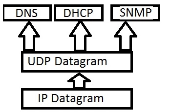
  • Provides basic application layer process multiplexing and de-multiplexing services through UDP source port and destination port number fields, as shown in the diagram below
Application Process De-Multiplexing by UDP
  • Supports a checksum feature for error detection purposes but this feature can optionally be disabled.
  • Does not have the concept of peer acknowledgment and hence unreliable
  • Does not support flow control and congestion control. Applications using UDP have to take care of flow/congestion control
  • Is best suited for applications that require fast data transfer but can tolerate slight loss of data
  • Is the preferred transport layer protocol for IP multicasting and real-time audio, video, multimedia applications, where fast delivery is more important than reliability
  • Is also used by simple client-server based application layer protocols where a quick response is required from a server, for a client request, without the overhead of connection establishment procedures (E.g. DNS, SNMP etc.)
  • Popular application layer protocols like SNMP, DNS, TFTP, RTP use UDP as the transport protocol

Basic Theory of Operation of UDP

UDP is just a simple extension to IP datagram service, where it provides application multiplexing and checksum computation of application data on the sending end and application  de-multiplexing and checksum verification on the receiving end.  It is a connection-less service, with no support for reliability, flow control and network congestion control.

UDP Encapsulation and Decapsulation

UDP Encapsulation and Decapsulations done at end computers

To achieve this, at the sending computer end, the UDP stack  encapsulates each piece of application data with a UDP header consisting of source and destination port numbers, apart from adding a checksum.

The UDP receiving process at the peer receiving end does the reverse operations. It first verifies the checksum to make sure that the UDP datagram came through the network uncorrupted and then uses the destination port number field to de-multiplex and hand over the application data to the appropriate application layer process.

UDP does not segment the incoming application data into streams of bytes. Hence, it is the responsibility of the application to segment the data as message blocks before handing it over to UDP layer.

Also the UDP layer at the receiving end drops erroneous UDP datagrams detected through checksum verification and it also drops UDP datagrams if there is no additional UDP buffers for storing it. In such cases, it does not inform the sender of dropped frames. Also there is no concept of UDP datagram numbering or acknowledgement. It is up to the application layer to take care of all these problems.


UDP Header and UDP Pseudo Header

The UDP header is a simple one consisting of just 8 bytes and includes only 4 fields. They are the source port number, destination port number, a length field specifying the length of the whole UDP datagram including the UDP Header and a Checksum field for error detection purposes, as given in the diagram below:

UDP Header
UDP Datagram (8 byte UDP Header + Application Data)

UDP Pseudo Header

UDP uses the whole UDP datagram and some fields from the IP header (termed as pseudo header) for computing the checksum, as shown in the diagram given below.

The UDP pseudo header

The reason for including the pseudo header is to verify that the UDP datagram is delivered to the right destination computer, as sometimes the IP header may get corrupted and the UDP datagram may arrive intact at the wrong destination.  The fields of the Pseudo header include the source and destination IP address of the IP packet that carries the UDP datagram, the IP protocol type field (UDP with a value of 0x11) and the total length of the UDP datagram.

Functional Overview of Transport Layer

This post gives a brief overview of the functions provided by the Transport Layer. Functions described include reliability, flow control, congestion control, application layer multiplexing/demultiplexing and sockets.

The Transport layer is the first layer from the bottom that is implemented and processed only on the communicating end nodes and not on intermediate nodes. While the physical, data link and network layer protocols are implemented and processed on end nodes as well as on intermediate nodes (Routers), the transport and application layers are implemented and processed only inside end computers (source and destination nodes). This means that intermediate network nodes like Routers are not involved in processing of the transport layer headers inside an IP datagram.

Positioning of Transport Layer :

The transport layer sits between the application layer and the network layer. On the sending node, the transport layer takes data from different applications, segments the data, adds the transport header and hands over the segment to the underlying network layer, to be delivered to the receiving node. On the receiving node, the transport layer receives segments from the underlying network layer, process the transport header and then hands over the application data to an application layer process.

Functions of Transport Layer :

The transport layer protocols are primarily responsible for

  •  End-to-End application data delivery between the source and destination computers using the underlying unreliable best-effort IP based networks. It provides either a byte stream or message based service to the application layer protocols. On the sending side, application data is split into a byte stream or into a series of message blocks, a transport layer header added and then transport layer segments are sent to the underlying IP layer in the sending node, to be delivered to the network. Once the IP network delivers the transport layer segments to the receiving machine, the transport layer process at the receiving machine processes the transport headers for reliability, flow and error controls and then hands over the application data to the appropriate application process.
  •  Application layer protocol Multiplexing/Demultiplexing for multiple applications communicating between end nodes. Multiplexing/Demultiplexing is provided using transport layer port numbers for providing multiple services like Email, Web browsing, file transfer over the same IP stack implementation on end nodes. For example, HTTP uses the reserved TCP port number 80, SMTP uses the reserved TCP port number 25, FTP control connection uses the reserved port number 21 etc. Similarly, DNS uses the reserved UDP port number 53, SNMP uses the reserved UDP port numbers 161 and 162. Normally, the transport layer header contains fields named as source port number and destination port number to uniquely identify the sending and the receiving processes respectively.
  •  End-End Reliability for making sure that every byte of sender’s application data reaches the receiver’s application, in order, in spite of travelling over a wide variety of unreliable telecommunication links. Reliability is taken care by using mechanisms like checksums, sequence numbers, acknowledgement numbers, timeouts and retransmissions.
  •  End-End Flow control for making sure that the sender sends data at a rate that the receiver can process and store. This is usually achieved  by the receiver advertising its current receiver buffer size continuously to the sender.
  •  End-End Congestion control for making sure that the sender does not introduce congestion in the intermediate network links and router buffers. Mechanisms like feedbacks from intermediate routers/receiver and monitoring receiver packet loss are used for controlling the sender rate so as not to congest the network links and router buffers.
  • Provides unique communication end points in the form of Sockets for applications to use the Networking stack of the machine to communicate externally
  • TCP, UDP are the most popular transport layer protocols

Note: Reliability, Flow control and congestion control are supported only in TCP and not in UDP.