A brief overview of Supernetting

This post gives a brief overview of Supernetting with examples.

Supernetting is the opposite of Subnetting. In subnetting, a single big network is divided into multiple smaller subnetworks. In Supernetting, multiple networks are combined into a bigger network termed as a Supernetwork or Supernet.

Supernetting is mainly used in Route Summarization, where routes to multiple networks with similar network prefixes are combined into a single routing entry, with the routing entry pointing to a Super network, encompassing all the networks. This in turn significantly reduces the size of routing tables and also the size of routing updates exchanged by routing protocols.

More specifically,

  • When multiple networks are combined to form a bigger network, it is termed as super-netting
  • Supernetting is used in route aggregation to reduce the size of routing tables and routing table updates

 Examples for Supernetting

Example – 1

Consider two networks with addresses 200.20.0.x/24 and 200.20.1.x/24. Both these networks have the same 23 bits network prefix and differ only in their 24th bit. Hence these two networks could be combined and summarized as a Super network with the address 200.20.0.x/23.

Note that the network mask has been reduced to 23 for the supernet. While subnetting borrows bits from the host portion of the IP address, supernetting borrows bits from the network portion of the IP address.

Example – 2

Similarly, if you take the four networks 200.20.0.x/24, 200.20.1.x/24 , 200.20.2.x & 200.20.3.x/24, they all have the same 22 bits network prefix and differ only starting from the 23rd bit. Hence these four networks could be combined into a single supernet as 200.20.0.x/22.

The diagram below illustrates this example of combining the four networks into a single Super network.

An example for Supernetting

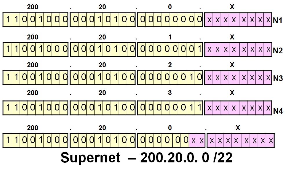
In the above example, all the four networks N1 to N4 have the same network prefix for the first 22 bits. Hence, Supernetting exploits this property and combines these four networks into a single Supernet, with a subnet mask of /22, for route aggregation purposes. Hence using this technique, four routing entries can be combined into a single routing entry, thereby reducing the size of routing tables and routing updates.

What is VLSM?

This post gives a brief overview of Variable Length Subnet Masks (VLSM) with an example

Variable Length Subnet Masks (VLSM) is nothing but having the flexibility to allot different sized subnetworks within a single network. That means that the number of subnet bits allotted to different subnetworks within a single network may not be the same for all subnetworks. VLSM is useful for partitioning the main network into different variable sized subnetworks, as would typically be the requirement in most of the organizations.

The example given below illustrates VLSM.

Example of a VLSM network with two different subnet masks used for different departments

In the diagram given above, the ISP has allotted 256 IP addresses to the organization, with the common IP address prefix 200.20.20.0. The number of nodes inside each of the three departments in the organization are different, with the Engineering department being bigger and requiring 128 IP addresses and the Accounts and HR departments requiring 64 IP addresses each. So, a variable sized subnetting strategy is used within the organization. Out of the 8 bits available for the end hosts (4th byte of the IP address), one bit (25th alone) is used as the subnet bit for the Engineering Subnet(/25 subnet mask). For the Accounts and HR department, two bits (bits 25 and 26 of the IP address) are borrowed from the host bits to be used for subnetting purposes.   This is just an example and we could even have subnets with just 4 addresses (/30 subnet mask).

The diagram given below illustrates the subnet masks represented in binary form for all the three subnets shown in the previous diagram.

Binary representation of subnet masks for the VLSM networks

As shown in the above diagram, the network prefix, consisting of the first 3 bytes is same for all the three subnetworks, namely 200.20.20.0. The variation comes in the 25th and 26th bits. For the Engineering subnet, 1 bit is allotted for the subnet and it has a value of 0. All the IP addresses in the Engineering subnet start with a value of 0 in bit position 25. For the Accounts and HR subnets, two bits are allotted for the subnet (bits 25 and 26). While bit 25 has a value 1 for both these subnets, bit 26 has a value of 0 for the HR subnet and bit 26 has a value of 1 for the Accounts Subnet. Since two bits are allotted for the subnet itself, only 6 bits are available for the end hosts for the Accounts and HR networks. This means that a total of 62 hosts (64 – 2 special addresses) can belong to each of these subnets. However, for the Engineering subnet, since 7 bits are available for the end hosts, there can be a total of 126 (128 – 2 special addresses) hosts in this subnet.

Thus, as illustrated in the above example, VLSM allows organizations to create different sized internal networks.