Overview of Switched WAN Networks

This post gives a brief overview of Switched WAN networks and their theory of operation.

Apart from point-to-point WAN Networks (where PPP is used), there is another type of WAN network known as switched WAN Network. As the name indicates, a switched WAN network is used to connect multiple end nodes through a common WAN network. The end nodes connect to a switched WAN network to either reach other nodes connected to the switched network or to connect to the public Internet.
X.25, Frame Relay, ATM, MPLS are examples of popular  switched WAN protocols.
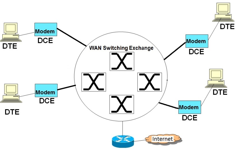
The diagram given below illustrates a typical switched WAN network
A typical Switched WAN Network
As shown in the above diagram, end nodes typically consist of DTE (Data Terminal Equipment) and DCE (Data Communicating Equipment) combinations. While the end computer is the DTE, the DCE is a modem that implements one of the switched WAN protocols (like X.25, ATM etc.) and is responsible for interfacing with the Switched WAN network. The Switched WAN network consists of multiple protocol specific WAN Switches (like ATM switches or  MPLS switches) that basically implement Layer 2 Switching of data frames. The Switched Network could act as a multi-point to multi-point network connecting the different end nodes or it could also act as a VPN (Virtual Private Network) connecting specific end nodes or end networks. The Switched WAN network is also typically connected to an external gateway router for enabling the end nodes to connect to the public Internet.

Basic Theory of Operation of Switched WAN Networks

All switched WAN networks work on the principle of  VC (Virtual Circuit) based packet switching. ( http://computernetworkingsimplified.com/physical-layer/overview-circuit-switching-packet-switching/ )

This implies that there would be a signalling phase and then a data transfer phase.

During the signalling phase, the WAN switches communicate among themselves using a signalling protocol to establish a virtual connection between the end points that need to communicate. As part of this signalling phase, a suitable path is determined and then VC table entries are created in each of the switches that are along the path of the communicating nodes. The VC table entries typically consists of protocol specific VC identifiers like ATM VPI/VCI, MPLS labels, Frame Relay DLCIs etc.

After the signalling phase, a virtual logical connection is established between the communicating end nodes through the switched WAN network. The actual data is then carried in Layer 2 frames (data transfer phase) with suitable VC Identifiers (VPI/VCI, labels etc.). The intermediate switches look at the VC Identifiers in the incoming frames, lookup the VC table for identifying the appropriate outgoing interface and also the outgoing VC Identifiers. It then replaces the incoming VC IDs with the outgoing VC IDs and sends out data frames via. appropriate outgoing interfaces.

As data is switched by looking at short VC IDs, the switching is faster than Layer 3 Routing (that used IP address lookup). Additionally, as there is an explicit signalling phase for VC establishment, QOS, and Traffic Engineering could be implemented easily by giving different priorities to different end flows, by marking VC entries with priorities. Similarly, point to point VPNs could also created between different end points by creating dedicated VC paths and giving unique VC IDs to the VPN connections.

Also both PVC (Permanent Virtual Ciruits) and SVC (Switched Virtual Circuits) are supported by these protocols. While leased lines use PVCs, general connections use SVCs.

While X.25 and Frame Relay use Frames as the basic unit of transmission, ATMs use fixed size cells as their basic data unit.
Basic Overview of the PPP protocol

This post gives a basic overview of the role of the PPP protocol and its theory of operation.

There are primarily two types of WAN links, namely point to point links and switched WAN links. PPP is the most popular data link layer protocol for point to point links. This post gives a brief functional overview of the PPP protocol.

Typical topology for PPP protocol usage

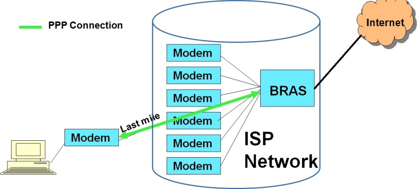
The diagram gives below a typical SOHO (small office/home office) user topology, with the user using the PPP protocol to connect to the Internet through the local ISP.

A SOHO topology where PPP is typically used

As seen from the diagram above, a typical SOHO topology consists of a WAN link (DSL/CableModem/Ethernet etc.)  to the local ISP. Modems at the user and ISP ends terminate the WAN connection. At the ISP end, the bank of modems connect to a Broadband Residential Access Gateway (BRAS). The BRAS connects the ISP network to the external Internet. The PPP protocol runs between the end user’s WAN link and the BRAS. The PPP protocol basically provides a dedicated point to point pipe to the ISP network, over which the user’s IP traffic is carried.

The Role of the PPP protocol

For the end user, PPP is a data link protocol providing the following services

  • Basic data link layer framing and de-framing services, to send Network layer data over the point to point network. The framing services include error detection as well.
  • An end user authentication framework for the ISP to uniquely authenticate each end user before allowing access to use the network resources. PPP framework supports usage of different authentication protocols like PAP, CHAP etc. for this purpose.
  • Facility to optionally enable data compression, so that data can be sent in compressed form over the PPP link.
  • Facility to carry different types of Network layer protocols (not only IP).
  • Facility to know the status of the peer end, by providing periodic keep alive messages.
  • Facility to operate over different types of physical links like DSL, cable modem, Ethernet, serial links etc..
  • Facility to combine multiple WAN links into a bigger point to point link, through the support of the multi-link PPP protocol.
  • PPP does not provide error correction, does not guarantee ordered delivery of frames, does not provide reliable delivery (frames corrupted or lost would have to be detected at the higher layers) and does not provide flow control.

 Basic overview of theory of operation of the PPP protocol

  • PPP’s frame structure has been derived from the HDLC (High Level Data Link Control) protocol. It has a simple frame structure (given in the diagram below).
PPP Frame Format
PPP Frame Format


  • As shown in the above diagram, a PPP frame is bounded on either ends with a fixed pattern Flag. The Address and Control fields have reserved values and are not used. The Protocol field carries the Network layer protocol type (IP, IPX etc.). The payload contains the actual network layer data and can be of variable length. The checksum is used for error detection purposes.PPP uses byte stuffing to detect flag patterns inside data.
  • PPP can be considered to have a link control phase and a data phase. In the initial link control or the link establishment phase, both peers exchange control information, exchange and negotiate link parameters using two protocols named LCP and NCP.
  • A protocol named as LCP (Link Control Protocol) is used to establish a logical link between the end points. The LCP facilitates negotiation of different link parameters between the end points like authentication protocol, enabling/disabling data compression, MTU (Maximum payload length) etc. The LCP also monitors the health of both ends by exchanging keep alive frames periodically between the end points.
  • After the LCP phase, PPP enters into the NCP (Network Control Protocol) phase, where the peers exchange network layer parameters. PPP supports a number of NCPs for negotiating network layer protocols. For example, PPP supports the IPCP (IP Control Protocol) for negotiating IP parameters, if the PPP link carrier IP packets (very typical). Using the NCP protocol, one can negotiate Network parameters like IP address, subnet mask etc. of the end user.
  • The LCP and NCP data are also carried inside PPP packets, with special protocol type values. These are called PPP control packets.
  •  After the successful completion of the LCP and the NCP phase, PPP enters into the data transfer phase, where it carries the actual network layer data (e.g. IP packets) inside PPP data frames.
  • At the end of the data transfer phase, both ends again exchange special LCP control packets to close the point to point link.
  • Originally, PPP was used mainly in WAN links. Due to its simplicity and powerfulness (especially authentication), it is now used even in LAN environments (For e.g. PPP over Ethernet).