What is a Layer2 Switch and how is it different from other network devices like Repeaters, Bridges and Routers?

This post gives a brief overview of the role of a L2 Switch. Additionally, it also talks about the differences between a L2 Switch and other network devices like Repeaters, Bridges and Routers.

A L2 Switch, at a very basic level, is a data link layer packet switch. Its main role is to forward data link layer frames from the source end node to the destination end node within a LAN, by looking at the destination MAC address in the frame header. It interconnects multiple end nodes of a LAN and intelligently forwards traffic between them without unnecessary flooding of frames onto the LAN. A L2 Switch comes with different types of interfaces like 10Mbps, 100 Mbps, 1 Gbps, 10 Gbps etc. and it also supports full-duplex communication on each of its port. It also facilitates network expansion and connecting to the rest of the network through high speed ports named as uplink ports that can be connected either to other L2 switches or to L3 Routers.
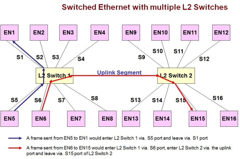
A sample Ethernet network with two L2 Switches and sixteen End Nodes (EN) is given in the diagram below:
A point to point Ethernet network with multiple L2 Switches

Difference between a L2 Switch and a Repeater

While a repeater is a physical layer device operating on electromagnetic and optical signals, a L2 Switch is a data link layer device that operates on L2 frames.

Also a repeater is mainly used to extend the length of a LAN segment or to increase the number of nodes in a LAN, while a L2 Switch is much more powerful and is actually used to intelligently transfer frames between the source and destination nodes of a LAN.

If a repeater is used to connect two segments of a LAN, then both segments form a single collision domain, as the repeater forwards every frame transmitted on one segment, unconditionally onto the other segment. On the other hand, if a L2 Switch is used to connect multiple segments of a LAN, then it helps to keep each segment as a separate collision domain. If nodes inside a same segment communicate with each other, then the traffic is confined to the segment by the L2 Switch. Only traffic between nodes across segments are forwarded across ports of a L2 Switch. This is illustrated in the diagram given below:
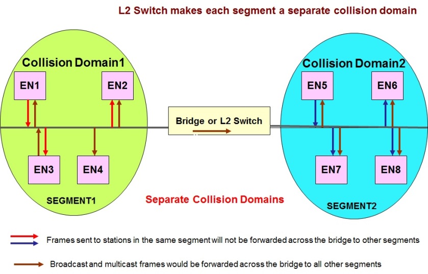
A L2 switch treats each segment connected to it as a separate collision domain.


Another difference is, though a Repeater comes with number of ports, all the ports are of the same speed, while a L2 Switch can have ports with different speeds. Additionally a single port in a L2 Switch is capable of working in different speeds based on the operating speed of the peer node connected to the port. Since L2 Switch supports multiple interface types, it can be even used to connect segments of a LAN with different technologies (e.g. a Ethernet segment and a Token ring segment).

Difference between a L2 Switch and a Bridge (Is there any?)

The answer is quite simple. A L2 Switch and a Bridge are not different and are one and the same. It is just that there are two terms for the same functionality.

Some time back, when internet was invented, the frame forwarding functionality of a L2 Switch was actually implemented in software and the device was known as a Bridge. Later when the same functionality was implemented in dedicated hardware, it was termed as a L2 Switch.

Additionally, in those days, a Bridge used to be one more device on the Ethernet bus just like any other device on the shared bus, with end nodes and the bridge tapping onto a common bus or connected to a hub. The Bridge was mainly used to connect different segments of a LAN in order to extend the LAN and also to keep each segment of a LAN as a separate collision domain. See the diagram given below that illustrates how a bridge was used to connect two segments of the same LAN.
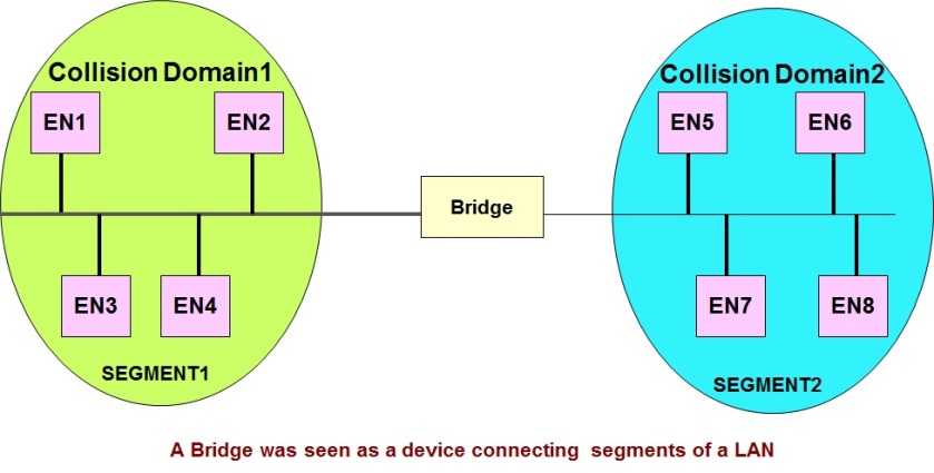
A Bridge was seen as a device connecting multiple segments of the LAN.

With the advent of dedicated hardware in the form of L2 Switches, end nodes could directly connect to ports of the L2 Switch through a dedicated point to point connection instead of tapping into a shared bus. See the diagram below that illustrates how a L2 Switch was seen:
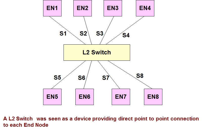
L2 switch was seen as a device that directly connects to each End Node.

This was perceived as one more difference between the original bridge and the L2 Switch.

All these differences no longer exist and now both the bridge and a L2 switch are functionally one and the same.

Difference between a L2 Switch and a L3 Router

Both L2 Switch and L3 Router are basically packet switches and both switch data based on a small header present in the data unit. The difference is that an L2 switch is a data link layer packet switch and switches data based on frame headers, whereas a L3 Router is a network layer packet switch and switches data based on the network header. Terminology wise, the functionality of a L2 Switch is typically known as Switching or Bridging and the functionality of a Router is typically known as Routing.

Also a L2 Switch is used to interconnect different segments of a same LAN or WAN, whereas a L3 Router is used to interconnect different networks or sub-networks.

While a L2 switch needs to implement only the physical and data link layer functionality, a L3 Router needs to implement the physical, data link layer and the network layer functionality. Due to this additional overhead, L2 Switches are typically faster than L3 Routers.

Another difference between a L2 Switch and a L3 Router is with respect to treatment of broadcast frames. While a L2 Switch forwards broadcast frames, a L3 Router does not forward broadcast frames, thereby limiting flooding of broadcasts over the network.

Typically, L2 Switches are used within a LAN, to extend the number of hosts in a LAN and also to reduce the collision domains in a LAN, whereas a L3 Router is used to connect the LAN to external networks.
Connectivity methods used in Ethernet Networks

This post gives a brief overview of the two basic methods of connecting end nodes in an Ethernet Network, namely bus and point to point connections. It illustrates each type of network with examples. It also includes an example for a hybrid Ethernet network consisting of both type of connections.

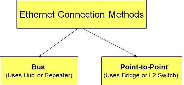
In Ethernet Networks, end nodes can be connected to the rest of the network primarily using two methods, namely a bus connection or a point to point connection as given in the diagram below:

End Node connectivity methods in Ethernet Networks

Bus Connection (Broadcast channel and single collision domain)

In the bus connection method, end nodes  attach to a common bus by connecting to either a Hub or a  Repeater. Since a hub or repeater just repeats the signal received on one port onto all other ports, this method of connection is equivalent to connecting to a common bus. Whenever an end node sends signals, it is heard by all other nodes connected to the hub or repeater. Hence this is a broadcast channel with a common collision domain (i.e if two end nodes transmit simultaneously, then a collision results).

A sample bus connection using a hub/repeater and four end nodes is given in the figure below:


A sample single collision domain bus network

In the above figure, though four end nodes are connected to the hub or repeater in a physical topology that looks like a star, the nodes are actually connected in a bus topology (as shown in the right portion of the diagram), because the hub or the repeater broadcasts the signals received on one of its port to all other ports.

The number of nodes in a bus topology network could be increased by connecting multiple hubs in a hierarchical fashion as given in the diagram below

A single collision domain hierarchical bus topology Ethernet network


Though there are multiple hubs and multiple segments in the network given above, the network is still a single collision domain network, as every node hears whatever every other node transmits.

The bus connections, though popular in olden days, is not used extensively these days, due to the availability of the better point to point switched networks.

Point-to-Point Connections (Switched or Bridged)

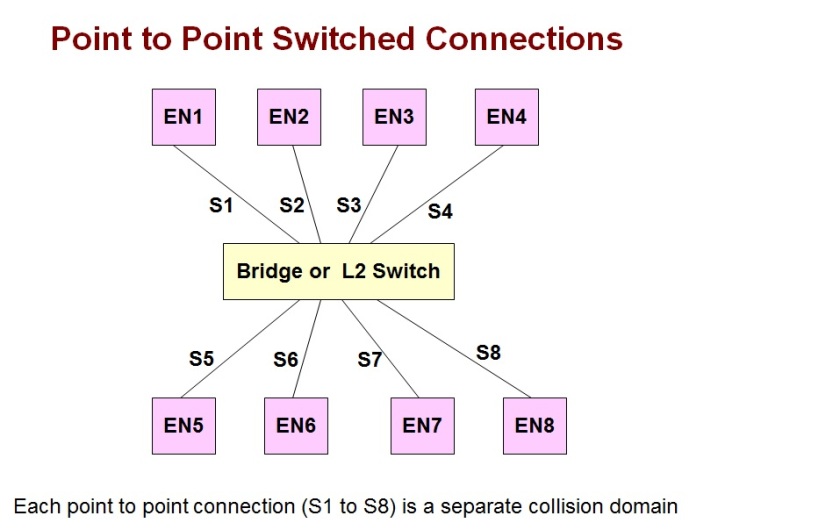
In this method of connecting end nodes, each end node has a dedicated point to point connection to a L2 switch (also known as bridge). An example point to point switched connection with eight end nodes is given in the diagram below:


An example Switched Ethernet Network

As given in the above diagram, though all the eight end nodes connect to the same L2 switch, they are still not part of a single collision domain, as the L2 switch does not broadcast signals received on one port on to all its other port. Instead a L2 switch intelligently forwards data (frames) only to the port that has the frame’s intended destination node. The L2 switch forwards data based on the destination node’s MAC address, that is present in the frame header. Due to this intelligence, each node’s link to the L2 switch is a separate collision domain. Also such point-to-point links are normally full duplex links and hence the node and the L2 switch could be simultaneously sending data to each other.

An example multiple L2 switch network

Apart from having point to point connections between end nodes and L2 Switches, there can be point to point connections between different L2 switches (normally called uplink ports), to form bigger networks with more hosts. An example of a sixteen node network interconnected by two L2 switches is given in the diagram below:

A point to point Ethernet network with multiple L2 Switches

 Hybrid Ethernet Topologies (Bus and point to point connections)

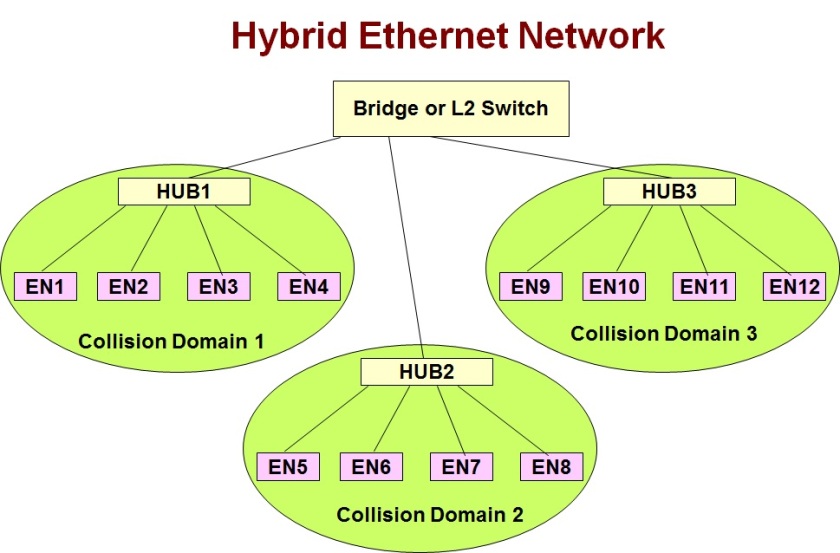
In order to make use of repeater or hubs that have already been purchased, some organizations and universities may still use a hybrid network consisting of both bus and point to point connections, as given in the diagram below:

A hybrid Ethernet network with hubs and L2 switch

In the above diagram, at the lower level, there are three separate collision domains, each served by a hub. At the next level, each hub has a point to point connection to a L2 switch.The L2 switch isolates the three collision domains and selectively forwards traffic between them. For example, if End Node 1 (EN1) sends a frame to End Node 2 (EN2), then the frame is heard by EN3 and EN4 too, as they are in the same collision domain. But the nodes in collision domain 2 and collision domain 3 do not get a copy of this frame, because the L2 switch filters out this frame based on the destination MAC address. Thus an L2 switch is able to limit the span of the collision domains in Ethernet networks and thereby improve overall throughput.