Basic Overview of the PPP protocol

This post gives a basic overview of the role of the PPP protocol and its theory of operation.

There are primarily two types of WAN links, namely point to point links and switched WAN links. PPP is the most popular data link layer protocol for point to point links. This post gives a brief functional overview of the PPP protocol.

Typical topology for PPP protocol usage

The diagram gives below a typical SOHO (small office/home office) user topology, with the user using the PPP protocol to connect to the Internet through the local ISP.
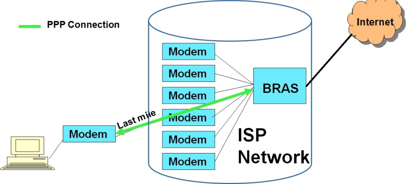
A SOHO topology where PPP is typically used

As seen from the diagram above, a typical SOHO topology consists of a WAN link (DSL/CableModem/Ethernet etc.)  to the local ISP. Modems at the user and ISP ends terminate the WAN connection. At the ISP end, the bank of modems connect to a Broadband Residential Access Gateway (BRAS). The BRAS connects the ISP network to the external Internet. The PPP protocol runs between the end user’s WAN link and the BRAS. The PPP protocol basically provides a dedicated point to point pipe to the ISP network, over which the user’s IP traffic is carried.

The Role of the PPP protocol

For the end user, PPP is a data link protocol providing the following services

  • Basic data link layer framing and de-framing services, to send Network layer data over the point to point network. The framing services include error detection as well.
  • An end user authentication framework for the ISP to uniquely authenticate each end user before allowing access to use the network resources. PPP framework supports usage of different authentication protocols like PAP, CHAP etc. for this purpose.
  • Facility to optionally enable data compression, so that data can be sent in compressed form over the PPP link.
  • Facility to carry different types of Network layer protocols (not only IP).
  • Facility to know the status of the peer end, by providing periodic keep alive messages.
  • Facility to operate over different types of physical links like DSL, cable modem, Ethernet, serial links etc..
  • Facility to combine multiple WAN links into a bigger point to point link, through the support of the multi-link PPP protocol.
  • PPP does not provide error correction, does not guarantee ordered delivery of frames, does not provide reliable delivery (frames corrupted or lost would have to be detected at the higher layers) and does not provide flow control.

 Basic overview of theory of operation of the PPP protocol

  • PPP’s frame structure has been derived from the HDLC (High Level Data Link Control) protocol. It has a simple frame structure (given in the diagram below).
PPP Frame Format
PPP Frame Format


  • As shown in the above diagram, a PPP frame is bounded on either ends with a fixed pattern Flag. The Address and Control fields have reserved values and are not used. The Protocol field carries the Network layer protocol type (IP, IPX etc.). The payload contains the actual network layer data and can be of variable length. The checksum is used for error detection purposes.PPP uses byte stuffing to detect flag patterns inside data.
  • PPP can be considered to have a link control phase and a data phase. In the initial link control or the link establishment phase, both peers exchange control information, exchange and negotiate link parameters using two protocols named LCP and NCP.
  • A protocol named as LCP (Link Control Protocol) is used to establish a logical link between the end points. The LCP facilitates negotiation of different link parameters between the end points like authentication protocol, enabling/disabling data compression, MTU (Maximum payload length) etc. The LCP also monitors the health of both ends by exchanging keep alive frames periodically between the end points.
  • After the LCP phase, PPP enters into the NCP (Network Control Protocol) phase, where the peers exchange network layer parameters. PPP supports a number of NCPs for negotiating network layer protocols. For example, PPP supports the IPCP (IP Control Protocol) for negotiating IP parameters, if the PPP link carrier IP packets (very typical). Using the NCP protocol, one can negotiate Network parameters like IP address, subnet mask etc. of the end user.
  • The LCP and NCP data are also carried inside PPP packets, with special protocol type values. These are called PPP control packets.
  •  After the successful completion of the LCP and the NCP phase, PPP enters into the data transfer phase, where it carries the actual network layer data (e.g. IP packets) inside PPP data frames.
  • At the end of the data transfer phase, both ends again exchange special LCP control packets to close the point to point link.
  • Originally, PPP was used mainly in WAN links. Due to its simplicity and powerfulness (especially authentication), it is now used even in LAN environments (For e.g. PPP over Ethernet).
Overview of VLAN and its basic theory of operation

This post gives an overview of VLAN. It describes the process of VLAN trunking, VLAN tagging, VLAN port types, VLAN classification methods. It also gives a brief overview of the basic theory of operation of a VLAN aware L2 Switch.

What is a VLAN

A Virtual LAN (VLAN), as its name indicates, is a virtual or logical separation of a LAN into multiple sub-LANs, with each sub-LAN  having its own members (end nodes).

VLANs are created mainly for administrative purposes to ensure that network traffic is seen only by members of a specific group, rather than by all members of the LAN. This way confidentiality is maintained and additionally nodes are protected from unnecessary traffic. For example, in an enterprise, each department (like Engineering, HR, Accounts etc.) may be maintained as a separate VLAN. Similarly, in a campus or a university network, each department (e.g. maths, physics, computer science  etc.) would typically be part of a separate VLAN.

An Example VLAN network

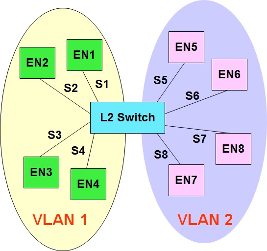
See the diagram below for an example of a network with two VLANs.

A sample L2 network with two VLANs.

In the above example, EN1 through EN4 belong to VLAN1 and EN5 through EN8 belong to VLAN2. The L2 switch ports S1 to S4 are configured to be part of VLAN1 and ports S5 to S8 are configured to be part of VLAN2.

L2 Broadcasts and Multicasts in VLAN aware L2 Switches

The main difference comes in the way L2 broadcast and multicast frames are handled by the L2 switches. If it is a single LAN (without VLANs), then the L2 switches forward the L2 broadcast and multicast frames to all members (end nodes) of the LAN (flooding). In case of a LAN being logically divided into multiple VLANs, then the L2 switch confines the flooding of the L2 broadcasts and multicasts frames only to members of a specific VLAN (which is the VLAN to which the end node transmitting the L2 broadcast/multicast frame belongs).

VLANs basically create separate broadcast domains within a network.

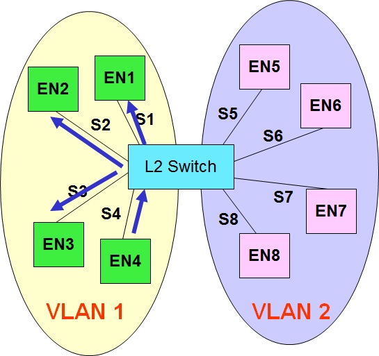
The example diagram below illustrates the handling of a L2 broadcast frame by a L2 switch.

An example of VLAN flooding by a L2 Switch

In this example, one of the members belonging to VLAN 1 (say EN4) transmits a L2 broadcast frame. The L2 switch recognizes that EN4 belongs to VLAN1 and hence floods the frame only to ports that belong to VLAN1. Thus the broadcast frame is forwarded only to EN1, EN2 and EN3. The frame is not sent out of ports 5 to 8, as these ports do not belong to VLAN1.

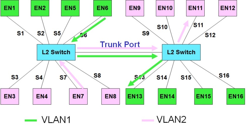
VLAN Port Types (Access and Trunk)

Ports in a VLAN enabled L2 Switch can be of two types, namely Access and Trunk Ports. Ports that carry traffic belonging to a single VLAN are termed as Access ports. Typically the ports connecting end nodes to a L2 Switch are Access ports, as end nodes typically belong to a single VLAN. Ports that carry traffic belonging to multiple VLANs are classified as Trunk Ports. Typically trunk ports are those that connect L2 Switches and those that connect a L2 switch to a L3 Router.

The diagram given below illustrates both types of ports.

VLAN Access and Trunk Ports

In the above diagram, all the 16 EN ports are access ports and the ports connecting the L2 Switches are the trunk ports. Each L2 switch has 4 End Nodes belonging to VLAN1 and another 4 End Nodes belonging to VLAN2. The diagram shows a sample frame on VLAN1 sent from EN6 to EN13 and another sample frame on VLAN2, sent from EN7 to EN11. Both frames travel via. the trunk ports connecting the two L2 Switches.

VLAN Tagging

In order for trunk ports to identify the VLAN corresponding to an incoming frame, frames sent on the trunk ports carry an additional 4 byte header named as the VLAN header inside the Ethernet frame. VLAN header is sandwiched between the L2 and L3 headers as shown in the diagram below:

An Ethernet frame with a 4 byte VLAN header
The VLAN header contains a VLAN-ID & Priority Fields. While the VLAN-ID field is used by the L2 switch to identify the VLAN to which a frame belongs to, the priority field is used for Quality of Service (QOS) purposes to give preferential treatment to frames during congestion.
VLAN Tagging is used mainly on trunk ports. Tagging is done to outgoing frames on trunk ports of L2 Switches and removed when it enters the peer L2 Switch.

 Basic Theory of Operation of a VLAN aware L2 Switch

The mechanism of operation of a VLAN aware L2 switch is similar to that of a normal L2 Switch in that basic L2 forwarding is done using ARL tables that are built by adaptive learning of end station’s MAC address.
However, in a VLAN aware switch, the primary difference comes in the number of ARL tables maintained. While a VLAN unaware L2 switch maintains a single ARL table, a VLAN aware L2 Switch maintains a ARL table for each VLAN that is under use. For example, if a L2 switch has members from two VLANs, then it maintains two ARL tables. The forwarding decision of frames belonging to a specific VLAN are taken by referring to the ARL table belonging to that specific VLAN. Within each VLAN ARL table, the learning, forwarding and time-out mechanisms remain similar to that of a normal L2 Switch.
A VLAN aware L2 switch needs to have the additional capability of flooding only to members of a specific VLAN and also implement the logic required for VLAN tagging in trunk ports.

Role of a L3 Router in a VLAN Network

While a VLAN aware L2 switch can forward frames from end nodes belonging to the same VLAN, it cannot forward traffic that needs to be sent from members belonging to different VLANs.  A L3 Router is required for this purpose.
Since a VLAN is a logical network by itself, each VLAN network is considered as a separate L3 Subnet and hence has a different L3 Subnet Address. Members belonging to different VLANs therefore need to have IP addresses belonging to different IP Subnets.
In summary, a L2 Switch is used for forwarding frames at layer 2 within a VLAN.  A L3 Router is used for sending inter-VLAN traffic. A L3 Router basically connects to multiple VLANs and routes traffic at L3 between these VLAN networks. While Intra-VLAN traffic is L2 Switched, inter-VLAN traffic is L3 Routed.

VLAN Configuration Methods

Since end nodes do not send VLAN tagged frames (tagging is used only on trunk ports by L2 Switches and L3 Routers), there has to be a method that enables a VLAN aware Switch/Router to identify the VLAN of each of its port. This is done by configuration of the Switch or Router based on three methods, namely port based or MAC address based or IP address based configuration.

In port based VLANs, each port of the L2 switch is configured with a specific VLAN ID. Typically, multiple ports would have the same VLAN ID (all members of a specific VLAN). For example, ports 1 to 4 could be configured to belong to VLAN ID 1 and ports 5 to 8 could be configured to belong to VLAN ID 2.
 In MAC based VLAN, the L2 Switch is configured with  MAC address-VLAN ID pair combinations, so that the L2 switch decides the VLAN of a frame based on this mapping and the source MAC address of the incoming frame.
In IP address based classification, the L2 switch identifies the VLAN ID of an incoming frame using the IP address present in the L3 header. In this case, the L2 Switch is configured with IP Subnet ID – VLAN ID pair combinations.