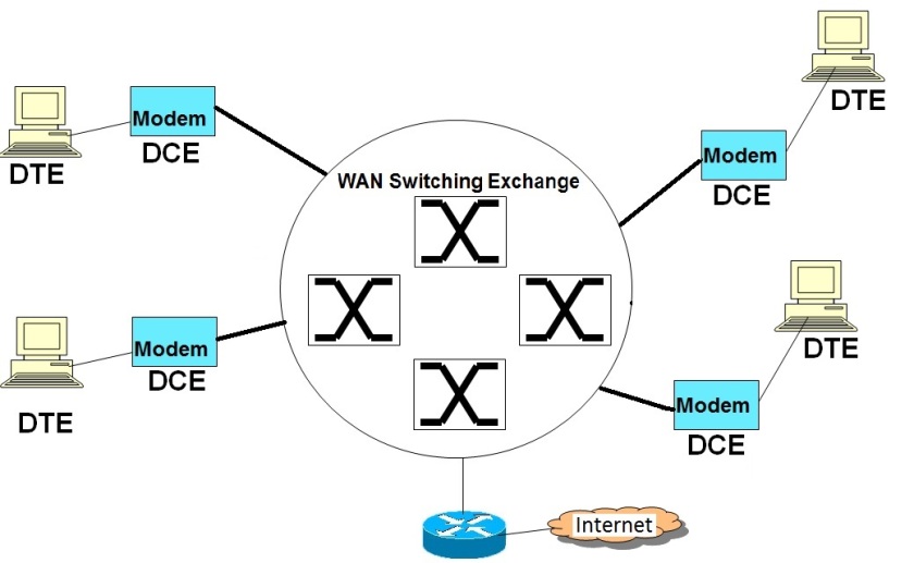
Basic Theory of Operation of Switched WAN Networks
All switched WAN networks work on the principle of VC (Virtual Circuit) based packet switching. ( http://computernetworkingsimplified.com/physical-layer/overview-circuit-switching-packet-switching/ )
This implies that there would be a signalling phase and then a data transfer phase.
During the signalling phase, the WAN switches communicate among themselves using a signalling protocol to establish a virtual connection between the end points that need to communicate. As part of this signalling phase, a suitable path is determined and then VC table entries are created in each of the switches that are along the path of the communicating nodes. The VC table entries typically consists of protocol specific VC identifiers like ATM VPI/VCI, MPLS labels, Frame Relay DLCIs etc.
After the signalling phase, a virtual logical connection is established between the communicating end nodes through the switched WAN network. The actual data is then carried in Layer 2 frames (data transfer phase) with suitable VC Identifiers (VPI/VCI, labels etc.). The intermediate switches look at the VC Identifiers in the incoming frames, lookup the VC table for identifying the appropriate outgoing interface and also the outgoing VC Identifiers. It then replaces the incoming VC IDs with the outgoing VC IDs and sends out data frames via. appropriate outgoing interfaces.
As data is switched by looking at short VC IDs, the switching is faster than Layer 3 Routing (that used IP address lookup). Additionally, as there is an explicit signalling phase for VC establishment, QOS, and Traffic Engineering could be implemented easily by giving different priorities to different end flows, by marking VC entries with priorities. Similarly, point to point VPNs could also created between different end points by creating dedicated VC paths and giving unique VC IDs to the VPN connections.
Also both PVC (Permanent Virtual Ciruits) and SVC (Switched Virtual Circuits) are supported by these protocols. While leased lines use PVCs, general connections use SVCs.
While X.25 and Frame Relay use Frames as the basic unit of transmission, ATMs use fixed size cells as their basic data unit.
