Examples for Subnet Creation

This post illustrates two examples for subnet creation. In the first example, an office network with two departments is taken and in the second example, an office network with four departments is taken.

This post illustrates two examples for subnet creation. In the first example, an office network with two departments is taken and in the second example, an office network with four departments is taken.

Example 1: An office network with two subnets  

Assume that the ISP has assigned the network 200.20.20.x with 256 IP addresses to the office and also assume that the office has two internal departments, namely Engineering and Accounts. The example splits this network internally into two equal subnetworks, so that each subnetwork can be used by a single department.

The diagram given below illustrates the office network with two departments and a subnet being created for each of the two departments

An office with two subnetworks

The diagram given below illustrates the basic splitting of the main ISP assigned address space into two internal subnets of equal size. Note that the first bit of the host (25th bit of the IP address space) is borrowed to create two subnets. The first subnet has a value of 0 in this bit position and the second subnet has a value of 1 in this bit position, as highlighted in green color in the diagram below:
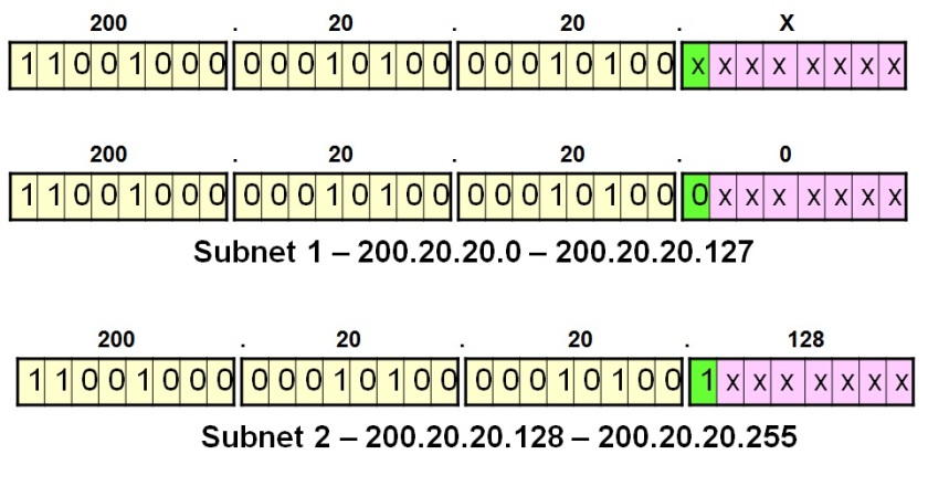
The main network being divided into two equal subnetworks internally

For each subnet created, the first and last address are treated as special addresses and reserved for specific purposes. While the first IP address in the subnet block (got by assigning a 0 to all host bit positions) is used to denote the subnet itself, the last IP address in the subnet block (got by assigning a 1 to all host bit positions) is used to denote the broadcast address within the subnet and is used whenever an IP packet need to be broadcast to all hosts inside a specific subnet.

The diagram given below illustrates the different addresses assigned to the first department (Accounts).
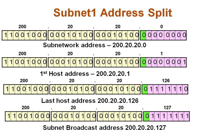
Allocation of IP addresses within the first subnet

The diagram given below illustrates the different addresses assigned to the second deparment (Engineering).
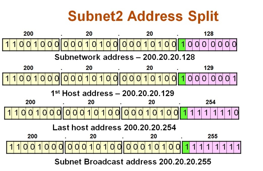
Allocation of IP addresses within the second subnet

Example 2: An office network with four subnets  

Assume that the ISP has assigned the network 200.20.20.x with 256 IP addresses to the office and also assume that the office has four internal departments, namely Engineering, HR, Marketing and Accounts. The example splits this network internally into four equal subnetworks, so that each subnetwork can be used by a single department.

The diagram given below illustrates the office network with four departments and a subnet being created for each of the four departments
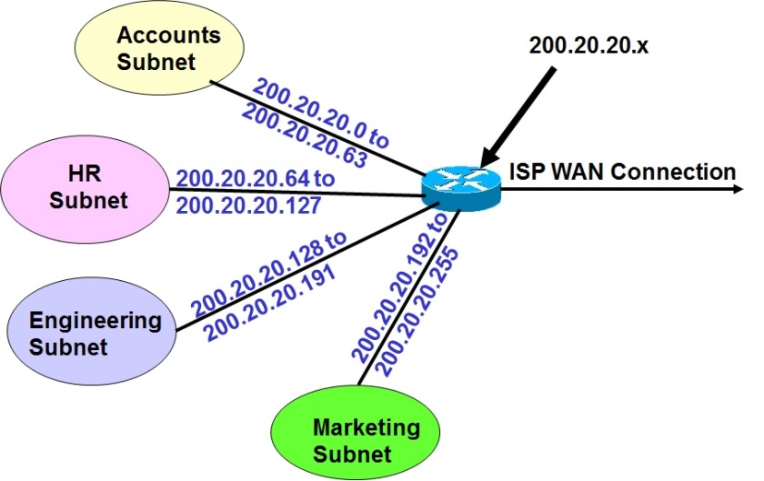
An office network with four internal subnets

The diagram given below illustrates the process of borrowing 2 bits from the host portion of the network, in order to create four subnets
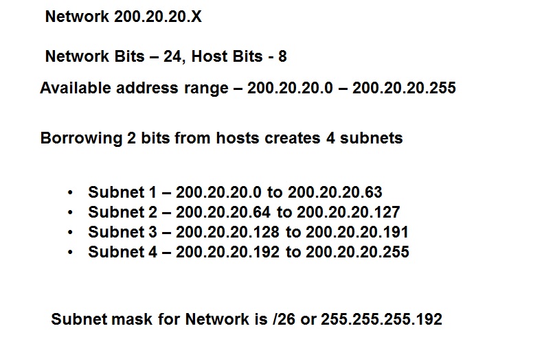
Four Subnets created from a single network

The diagram given below illustrates the basic splitting of the main ISP assigned address space into four internal subnets of equal size. Note that the first two bits of the host (25th and 26th bits of the IP address space) are borrowed  to create four subnets. The first subnet has a value of 00, the second subnet has a value of 01, the third subnet has a value of 10 and the fourth subnet has a value of 11 in these two bit positions allotted for the subnet, as highlighted in green color in the diagram below:
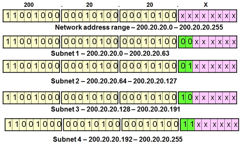
IPsubneteg21
Four subnets with their IP address assignment shown in binary format

The diagram given below illustrates the different addresses assigned to the first department (Accounts).
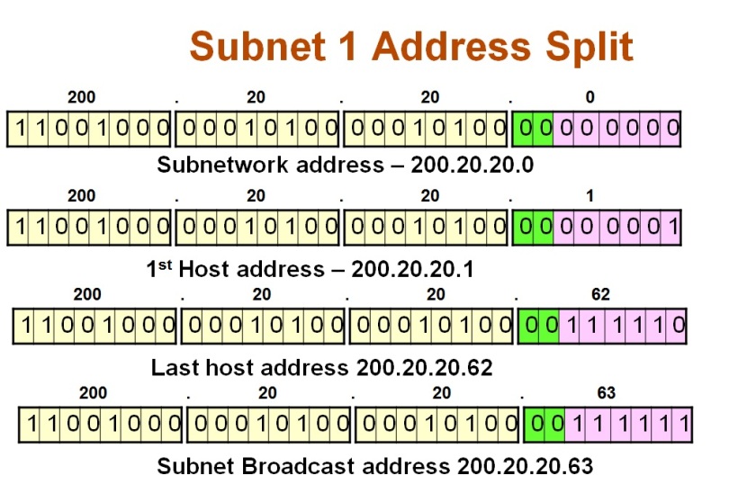
IP address assignment inside Subnet 1

The diagram given below illustrates the different addresses assigned to the second department (HR).
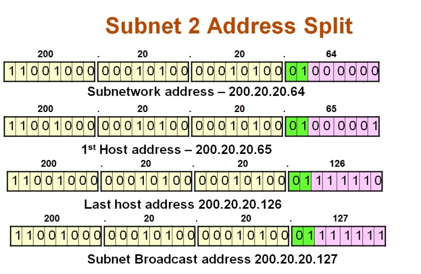
IP address assignment inside Subnet 2

The diagram given below illustrates the different addresses assigned to the third department (Engineering).
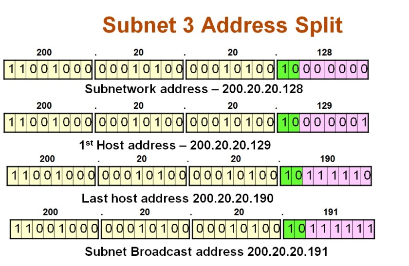
IP address assignment inside Subnet 3

The diagram given below illustrates the different addresses assigned to the fourth department (Marketing).
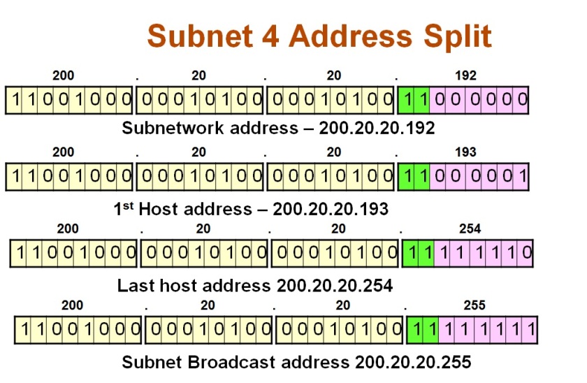
IP address assignment inside Subnet 4

A brief overview of IP Subnetting

This post gives a brief overview of the concept of IP Subnetting with an example. It also describes the concept of IP subnet mask.

IP Subnetting is the process of partitioning a bigger network into smaller networks by making use of some portion of the IP addresses normally allotted to hosts (i.e. one or more bytes are borrowed from the host portion of the IP address to partition the main network into different sub networks).

It is typically used when there is an administrative need to have more networks internally with lesser number of hosts in each of these small networks rather than a single big network with large number of hosts.

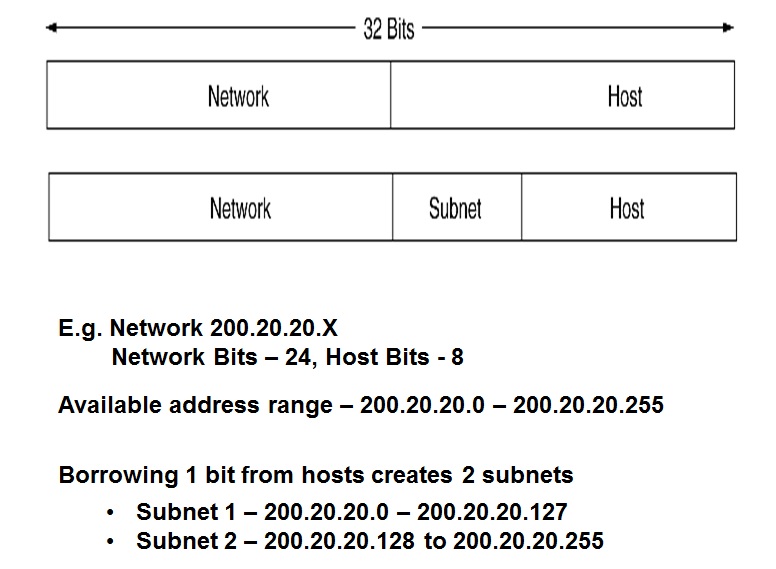
The concept of borrowing host bits to create subnets is illustrated in the diagram given below:

Two IP Subnets created by borrowing one bit from the host portion

The above example splits a single big network (200.20.20.0) with 255 hosts into two equal smaller subnetworks (200.20.20.0 and 200.20.20.128), each with 128 IP addresses.

Subnet Mask

  • Subnet mask is similar in format to IP address : E.g. a.b.c.d
  • It contains a one for bit positions belonging to the network or subnetwork and contains a zero for the host portion
  • For example, the default subnet masks for class A, B and C are:
    • Class A – 255.0.0.0 or FF.0.0.0 or /8
    • Class B – 255.255.0.0 or FF.FF.0.0 or /16
    • Class C – 255.255.255.0 or FF.FF.FF.00 or /24

Note that the subnet masks can be denoted in three different formats as shown above. The first form (e.g. 255.0.0.0) is in decimal notation, the second form (e,g.FF.0.0.0) is in hexadecimal notation and the third form (e.g. /8) is in the /no-of-bits-for-network-and-subnetwork format.

In the above example, /8 for class A denotes that 8 bits are allotted to the network and subnetwork put together and the remaining 24 bits are for the host portion.


Getting the Subnet Address from the Host IP address and Subnet Mask

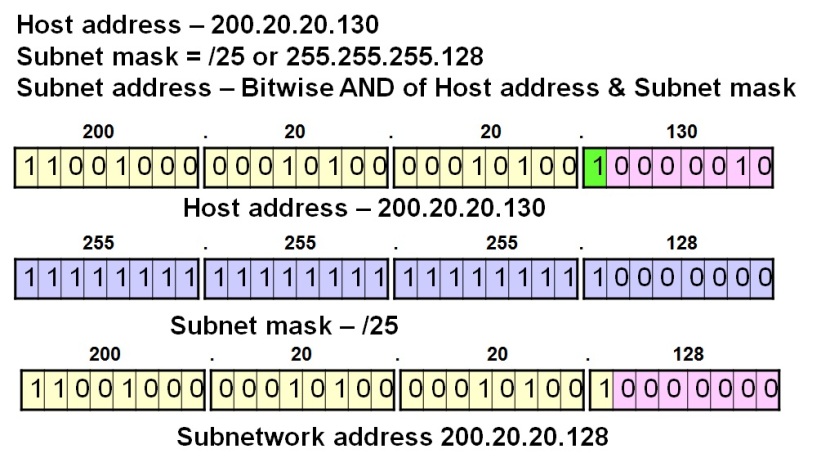
If we are given an end host address and the subnet mask, then we can get the subnetwork address by bit wise AND operation of the above two. The example in the diagram given below illustrates the same:

Getting the subnet address from the host IP address and the subnet mask


The above diagram illustrates the method used to get the subnetwork address, given an end host IP address and the subnet mask used in the network.