This posts describes the relationship between signal bandwidth, channel bandwidth and maximum achievable data rate. Before, going into detail, knowing the definitions of the following terms would help:
- Signal Bandwidth – the bandwidth of the transmitted signal or the range of frequencies present in the signal, as constrained by the transmitter.
- Channel Bandwidth – the range of signal bandwidths allowed by a communication channel without significant loss of energy (attenuation).
- Channel Capacity or Maximum Data rate – the maximum rate (in bps) at which data can be transmitted over a given communication link, or channel.
If we take analog transmission line coding techniques like Binary ASK, Binary FSK or Binary PSK, information is tranferred by altering the property of a high frequency carrier wave. If we increase the frequency of this carrier wave to a higher value, then this reduces the bit interval T (= 1/f) duration, thereby enabling us to transfer more bits per second.
Similarly, if we take digital transmission techniques like NRZ, Manchester encoding etc., these signals can be modelled as periodic signals and hence is composed of an infinite number of sinusoids, consisting of a fundamental frequency (f) and its harmonics. Here too, the bit interval (T) is equal to the reciprocal of the fundamental frequency (T = 1/f). Hence, if the fundamental frequency is increased, then this would represent a digital signal with shorter bit interval and hence this would increase the data rate.
So, whether it is analog or digital transmission, an increase in the bandwidth of the signal, implies a corresponding increase in the data rate. For e.g. if we double the signal bandwidth, then the data rate would also double.
In practise however, we cannot keep increasing the signal bandwidth infinitely. The telecommunication link or the communication channel acts as a police and has limitations on the maximum bandwidth that it would allow. Apart from this, there are standard transmission constraints in the form of different channel noise sources that strictly limit the signal bandwidth to be used. So the achievable data rate is influenced more by the channel’s bandwidth and noise characteristics than the signal bandwidth.
Nyquist and Shannon have given methods for calculating the channel capacity (C) of bandwidth limited communication channels.
Nyquist Criteria for maximum data rate for noiseless channels
Given a noiseless channel with bandwidth B Hz., Nyquist stated that it can be used to carry atmost 2B signal changes (symbols) per second. The converse is also true, namely for achieving a signal transmission rate of 2B symbols per second over a channel, it is enough if the channel allows signals with frequencies upto B Hz.
Another implication of the above result is the sampling theorem, which states that for a signal whose maximum bandwidth is f Hz., it is enough to sample the signals at 2f samples per second for the purpose of quantization (A/D conversion) and also for reconstruction of the signal at the receiver (D/A conversion). This is because, even if the signals are sampled at a higher rate than 2f ( and thereby including the higher harmonic components), the channel would anyway filter out those higher frequency components.
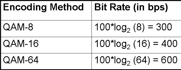
Also, symbols could have more than two different values, as is the case in line coding schemes like QAM, QPSK etc. In such cases, each symbol value could represent more than 1 digital bit.
Nyquist’s formulae for multi-level signalling for a noiseless channel is
C = 2 * B * log M,
where C is the channel capacity in bits per second, B is the maximum bandwidth allowed by the channel, M is the number of different signalling values or symbols and log is to the base 2.
- If binary signals are used, then M= 2 and hence maximum channel capacity or achievable data rate is C = 2 * 3000 * log 2 = 6000 bps.
- Similarly, if QPSK is used instead of binary signalling, then M = 4. In that case, the maximum channel capacity is C = 2 * 3000 * log 4 = 2 * 3000 * 2 = 12000bps.
Shannon’s channel capacity criteria for noisy channels
C = B log (1 + S/N)
(log is to base 2)
For example, for a channel with bandwidth of 3 KHz and with a S/N value of 1000, like that of a typical telephone line, the maximum channel capacity is
Using the previous examples of Nyquist criteria, we saw that for a channel with bandwidth 3 KHz, we could double the data rate from 6000 bps to 12000 bps., by using QPSK instead of binary signalling as the line encoding technique. Using Shannon’s criteria for the same channel, we can conclude that irrespective of the line encoding technique used, we cannot increase the channel capacity of this channel beyond 30000bps.
In practise however, due to receiver constraints and due to external noise sources, Shannon’s theoritical limit is never achieved in practise.
- In general, greater the signal bandwidth, the higher the information-carrying capacity
- But transmission system & receiver’s capability limit the bandwidth that can be transmitted
- Available bandwidth for transmission
- Channel capacity and Signal-to-Noise Ratio
- Receiver Capability
